Overview
At a high level, the power system consists of a pair of NiMH batteries which distribute power to the motors, sensors, processors, and accessory subsystems. The batteries, each supplying 7.2V, are wired in series and connected directly to a shield that links the four DRV8825 stepper motor drivers to the motor control arduino. In parallel with the motor controllers are two accessory buses. The first is a 9V bus, powering the two arduino boards. The second, is a 5V bus, which powers the speaker and payload deployment servo. This streamlined power distribution system delivered consistent power to all subsystems, while maximizing motor power.
Motors
The stepper motors are powered using DRV8825 stepper motor driver modules, with all four connected to the motor control arduino board with an expansion shield. The DRV8825s allow for independent motor current control, allowing us to deliver the maximum rated current to each of our NEMA 17 stepper motors, 1.5A. At 1.5A, each motor delivers 42 N/cm of torque. Based on intial estimations for toruqe requirements, the bot only needed 9.4 N/cm per wheel to meet the highest torque demand, which would occur during the ramp climb. See the image below for details on the calculations. This highlights the benefit of a four-wheel drive system. Though it demanded a significant amount of power, up to six amps at peak, it provided ample torque. Even when the team upgraded to wheels with a larger diameter, increasing peak torque demand to 15 N/cm, the motors far exceeded that need.
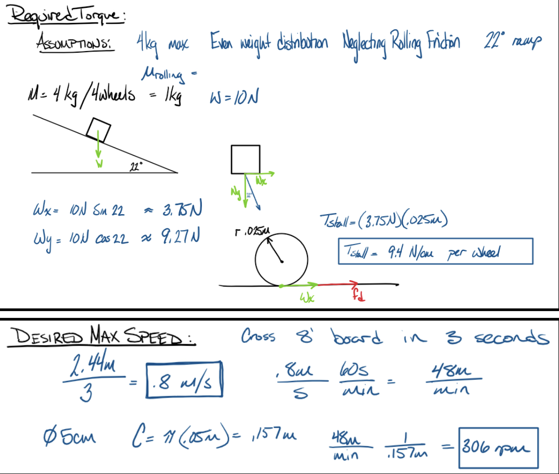
Speed requirements were also well within the range of our NEMA 17 motors. Even intially, 5 cm wheels were installed, resulting in a targeted maximum speed of 306 rpm. Detailed calculations can be found in the image above. Similar to our torque delivery, the motors were more than able to meet our demand for high speed operations. When we later installed larger diameter wheels, our speed increased further, requiring us to operate well below maximum capacity due to small size of the playing field.
Power Subsystems
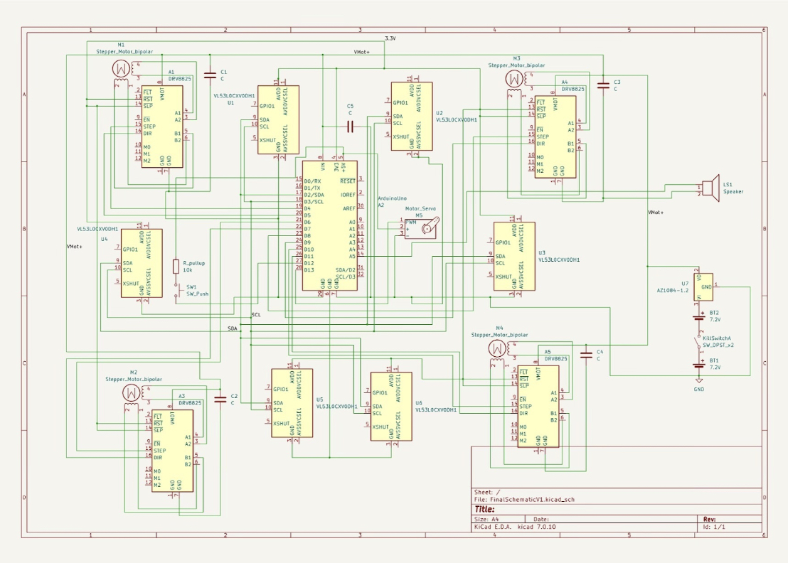
Three subsystems were used to power the bot. The motors received up to 18.5V directly from the two nickel metal hydride, 6-cell batteries providing up to 3600mAh. In parallel with that system are two variable voltage buck converters powering a 9V bus and a 5V bus. The 9V bus powered the two ardunios, which in turn powered the four LiDAR sensors off of the Ardunio's 5V power supply. The relatively high current loads of the payload deployment system servo and the celebration speaker exceeded the capacity of the Ardunio, necessitating the addition of the separate 5V bus to power those accessories.
Components List
- 2x 7.2V nickel metal hydride, 6-cell batteries providing up to 3600mAh
- 2x Variable voltage buck converters
- 4x DRV8825 stepper motor controllers
- 4x 1.5A, Bipolar, Nema 17 Stepper Motors
- 1x Arduino board expansion shield